
Aluminium Scaffold Braces & Snap-Lock Claws: Horizontal vs. Diagonal Bracing, Trigger Lock Retention, Riveted vs. Welded Joints & EN 1004-1 Procurement Guide (2026)
Compare aluminium scaffold braces, snap-lock retention and riveted vs welded joints. Use the EN 1004 evidence checklist to specify parts and request a quote.
Buyer takeaway: Select aluminium scaffold braces by the tower manufacturer's approved part schedule, connection geometry and documented retention performance. Horizontal and diagonal members serve different functions; a matching tube diameter or familiar trigger colour cannot establish interchangeability.
This guide helps procurement teams, rental fleet managers and temporary works coordinators compare replacement braces and complete bracing packages for mobile aluminium scaffold towers. It turns connection, inspection and documentation questions into an RFQ that suppliers can answer against identifiable parts.
Reviewed 10 November 2026. Scope: Global, English-language procurement guidance for prefabricated mobile towers. European design standards, US construction rules and Australian product notices have different purposes and jurisdictional limits. This is a document-review and purchasing framework, not a tower design, assembly manual, product test report or certification. No physical brace testing was performed for this guide. Numeric geometry examples below are calculations, not measured product specifications.
Already replacing a known component? Send the tower model and brace part number for a sourcing enquiry. Include photographs of markings and both connection ends so compatibility questions can be resolved before a quotation becomes an order.
1. Mechanical Anatomy: Horizontal vs. Diagonal Braces
A prefabricated tower depends on the interaction of frames, braces, platforms, stabilisers and connections. Vertical frames carry gravity loads, while the specified bracing arrangement controls alignment and resists lateral deformation. The bill of materials changes with tower model, configuration and height; there is no useful universal brace count for an “8 m tower.” Distinguish platform height, overall height and advertised working height when comparing packages.
Horizontal Braces: Spacing and Specified Guardrail Duties
Horizontal braces maintain the separation of connected members at the locations shown in the manual. Some are also used as guardrails or intermediate rails in approved assemblies. A horizontal member is not automatically suitable for either duty merely because it reaches between the frames.
For purchasing, record whether the member is a base brace, structural tie, intermediate rail or top rail. Ask which frame member each claw engages and which direction the hook faces. Guardrail levels, allowable openings and installation sequence must follow the approved design and destination requirements. A generic instruction to place rails at exactly 0.50 m and 1.00 m cannot replace that information.
A supplier may quote a lower price for a shorter brace that appears almost identical. If it has different seating centres, forcing it into place can introduce frame distortion or leave the fitting only partly seated. Resolve the part identity before discussing finish, packaging or colour.
Diagonal Braces: Racking Resistance and Load Path
Diagonal braces create triangular load paths within a bay, reducing the tendency of a rectangular arrangement to rack sideways. Real frame joints have finite stiffness; the simplified pinned rectangle is an explanation of the bracing principle, not a claim that every unbraced frame has literally zero stiffness.
A diagonal can carry tension or compression depending on the load direction. Compression capacity depends on tube geometry, unsupported length and end restraint, while connection capacity depends on seating, latch geometry and the end joint. An apparently stronger tube cannot compensate for an unsuitable claw.
Use the manufacturer's layout for the number, direction and attachment levels of diagonals. An illustrative zigzag does not establish a bracing schedule. Netting, sheeting, cantilevers or bridges change the loading or configuration and require specific approval. Remove people and loose materials before moving a tower, and follow its relocation instructions; bracing is not permission to move an occupied or loaded tower.
2. Snap-Lock Claw Engineering and Trigger Retention
A snap-lock fitting generally combines a shaped jaw, a moving latch, a return mechanism and a deliberate release control. Designs vary: a visible spring, a certain jaw wrap angle or a particular casting alloy does not by itself prove that the connection will remain engaged under the required actions.
Ask the supplier to identify the mating frame tube outside diameter and tolerance, the seating surface, latch travel, release action and inspection points. A 50.8 mm tube is an example encountered in tower specifications, not a universal interface. Two fittings designed around the same nominal diameter can have different offsets, contact surfaces and permitted orientations.
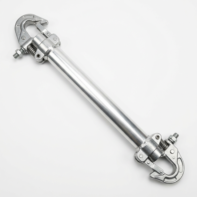
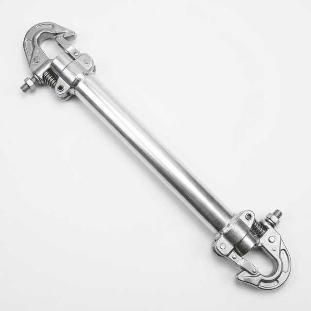
Figure 1. Existing catalogue image of a brace and its metal end fittings. It does not show installation on a frame, prove snap-lock engagement, or verify dimensions, materials or certification.
Specify Retention Performance Before Spring Material
A return spring helps close a latch; the retained load path also depends on the jaw, catch, pivot and seating geometry. Do not confuse trigger closing force with connection retention capacity. A latch that sounds decisive can still have damaged contact surfaces or incomplete engagement.
Request the applicable retention test method, load direction, fixture, acceptance criterion and result for the exact brace/frame assembly. Ask whether the report covers new parts only and whether any durability or environmental conditioning was included. Where a supplier proposes a cycle count or salt-spray duration, establish the test conditions and reason for that target in the purchase specification. This guide does not establish universal EN minima for uplift, axial force, spring wire size or cycle life.
Specify corrosion resistance and material traceability appropriate to the environment, then ask how the spring and adjoining metals meet those requirements. Stainless steel can be a design choice; an alloy label alone does not guarantee fatigue life or prevent a mechanism from sticking. Cleaning and lubrication must follow the manufacturer, because an unsuitable lubricant can retain debris or affect other parts.
What the Australian Yellow-Hook Recall Actually Shows
The Product Safety Australia notice for Oldfields yellow-hook horizontal guardrail braces, published on 13 June 2024, reports that the locking mechanism may fail to close properly, allowing detachment and creating a fall hazard. Its listed models and serial range determine affected stock; colour alone is insufficient identification. Owners are instructed to stop using affected products and follow the recall process.
The notice does not identify spring metallurgy, hydrogen embrittlement or casting flash as the root cause. For buyers, the practical lesson is to keep component identities and recall records accessible. A fleet register should connect purchased parts to supplier, delivery lot, applicable model and any recall action. A successful hand check cannot clear a component covered by a stop-use notice.
3. Riveted Insert Plugs vs. Welded Necks
Both mechanically fastened and welded end fittings can form part of a validated tower system. Compare the complete connection and maintenance policy rather than treating either manufacturing method as a substitute for engineering evidence.
Riveted Insert Plug Architecture
An insert spigot enters the tube and is secured with specified fasteners. Riveting avoids a welding heat-affected zone, but the drilled holes, remaining tube section, bearing stresses and fastener installation still require design control. The presence of rivets does not preserve “100% strength” of the assembled brace.
Request the insert drawing, fastener identity, hole preparation and installation criteria. Inspect for loose heads, fretting, cracks, corrosion and relative movement. Dissimilar materials and trapped moisture can influence corrosion performance, so the coating, drainage and exposure conditions matter alongside the alloy specification.
A riveted connection is repairable only if the manufacturer provides an authorized procedure. That procedure should identify replacement parts, acceptable tube condition, tooling, personnel competence and final checks. Drilling out a damaged fitting without those controls can enlarge holes or return an unsuitable tube to service.
Welded Neck Architecture
A welded fitting needs a suitable material combination, welding procedure and inspection plan. Heat can alter the local properties of heat-treated aluminium, so the designer must account for the weld and adjacent material. A universal 40–50% strength reduction cannot be assigned to every alloy, joint or load case.
Neither a smooth weld bead nor automation proves penetration or fatigue performance. Ask how weld quality and production consistency are controlled and which test report covers the supplied assembly. A circumferential weld is not proof that the tube is hermetically sealed; drainage and moisture control must be established from the design. Repair, if permitted, also needs manufacturer approval.
Engineering and Procurement Comparison Matrix
| Procurement question | Riveted insert plug | Welded neck | Evidence to request |
|---|---|---|---|
| Local material effects | No welding heat; holes reduce local section | Welding changes local material properties | Connection design basis and assembly test |
| Load transfer | Fastener shear, bearing and insert contact | Weld throat and adjoining material | Report with loads, fixtures and acceptance criteria |
| Fatigue concerns | Fretting, fastener or hole damage | Weld detail and adjacent material damage | Applicable duty assumptions and durability evidence |
| Production control | Hole size, rivet identity and setting | Procedure, preparation and inspection | Lot inspection records and process controls |
| Corrosion concerns | Crevices and dissimilar-metal interfaces | Alloy, weld condition and moisture paths | Environment-specific protection plan |
| Repairability | Only with an authorized replacement procedure | Only if an authorized repair exists | Written repair and release instructions |
| Traceability | Tube, insert and fastener identity | Tube, fitting and welding records | Link from delivered lot to approved design |
| Receiving checks | Loose heads, movement, cracks or distortion | Cracks, distortion or suspect weld condition | Manufacturer's inspection criteria |
| Cost comparison | Include approved parts, labour and inspections | Include replacement or approved repair costs | Comparable lifecycle assumptions |
| Approval decision | Accept only for the identified tower system | Accept only for the identified tower system | Exact model and component schedule coverage |
For fleet costing, compare purchase price plus expected inspection, authorized maintenance, downtime and replacement over the same service period. Use your recorded damage rate and labour cost. A lower unit price or a modular-looking fitting does not establish lower lifetime cost without those inputs.
4. Visual Engineering Architecture and Claw Mechanics
The schematic below illustrates a latch and a triangulated bay. It is conceptual and not to scale. Colours, spring placement and fastener arrangement are examples; it omits platforms, complete edge protection, stabilisers and other required components. It must not be used to assemble or qualify a tower.
5. Geometry, Bay Matching and Colour Identification
Center-to-Center Length Calculation
For two ideal attachment centres in one plane, use Ld = √(Lb² + Hr²), where Lb is their horizontal separation and Hr their vertical separation. With Lb = 2.50 m and Hr = 2.00 m, Ld = √10.25 ≈ 3.202 m. This reproducible calculation checks a drawing; it does not select an available replacement part.
Real fittings have offsets, orientations and seating profiles. Catalogue “bay length” may not equal the attachment-centre separation used in this equation. Record whether a quoted dimension is overall length, seat-to-seat length or another datum. Request both an approved part number and a dimensioned drawing before ordering.
Illustrative Geometry Table
All lengths below are calculated from the stated ideal centres and rounded to the nearest millimetre. They are not stock dimensions, manufacturing tolerances, tube specifications or approved tower configurations. Hr = 0 identifies a horizontal example, not authorization to use a particular guardrail.
| Horizontal separation Lb | Vertical separation Hr | Calculated distance Ld | Geometry example |
|---|---|---|---|
| 1.80 m | 0.00 m | 1,800 mm | Horizontal |
| 1.80 m | 1.00 m | 2,059 mm | Diagonal |
| 2.00 m | 0.00 m | 2,000 mm | Horizontal |
| 2.00 m | 1.00 m | 2,236 mm | Diagonal |
| 2.50 m | 0.00 m | 2,500 mm | Horizontal |
| 2.50 m | 1.00 m | 2,693 mm | Diagonal |
| 2.50 m | 2.00 m | 3,202 mm | Diagonal |
| 3.00 m | 0.00 m | 3,000 mm | Horizontal |
| 3.00 m | 2.00 m | 3,606 mm | Diagonal |
There is no universal brace colour code established by the sources cited here. Red and blue in the schematic distinguish functions visually; another manufacturer's colours may differ. Use part markings, measured datums and the manual together, and segregate unidentified stock until its origin and suitability are resolved. Never force a member to fit.
Platform and access arrangements also affect the configuration: see the aluminium scaffold platforms procurement guide. For a missing drawing or ambiguous replacement, request a component compatibility review with the existing part information.
6. Global Standards: Match the Evidence to the Destination
European Design Scope and Non-Standard Towers
The BSI scope preview for BS EN 1004-1:2020 covers prefabricated mobile access and working towers up to 12 m indoors and 8 m outdoors. It addresses the complete tower. A component quotation should therefore identify the tower configuration and evidence within which that brace is approved.
The public preview does not substantiate the detailed clause numbers or generic connection test values sometimes repeated in sales literature. Verify exact requirements in the licensed standard and relevant report. Ask for the issuer, report number, model coverage and limitations of any certificate before accepting an EN claim.
PASMA's EN 1004 revision guide explains the distinction between standard mobile towers and configurations such as cantilevers, linked towers or towers on baseplates, and points to BS 1139-6 for towers outside EN 1004's scope. It is revision-era guidance, not a substitute for the current standard, manual or a project-specific design. Do not infer a universal diagonal pattern from a standard's name.
US Construction Requirements
OSHA 29 CFR 1926.451 provides general scaffold requirements; paragraph (e)(1) prohibits using crossbraces for access. Paragraph (g)(4)(xv) permits crossbracing in place of a midrail or toprail only with specified crossing heights and end-point spacing. Those conditional provisions do not make any diagonal a compliant guardrail. Apply the complete relevant rules and the approved configuration.
Australia, New Zealand and Other Destinations
Confirm the locally applicable standards, editions, workplace rules and acceptance process with the destination duty holder. If a contract specifies the AS/NZS 1576 series, ask which parts apply to the exact system and what evidence supports them. An EN claim or an Australian recall notice does not establish local compliance. Agree this evidence package before dispatch rather than attempting to resolve it at site handover.
7. Rental Yard Receiving, Maintenance and Quarantine
Receiving inspection should answer two separate questions: is this the ordered, approved part, and is its condition acceptable? Match delivery quantities and markings to the order, preserve lot records, and compare supplied documentation with the approved revision. Photograph discrepancies before distributing stock across depots.
Practical Inspection Checklist
- Identity: Model, part number and relevant lot markings match the order and tower schedule. Unidentified or potentially recalled parts remain segregated.
- Seating: On the specified matching frame, the claw seats as described in the manual without forcing or visible interference.
- Latch operation: The mechanism closes fully and releases through the intended action. Sticking, incomplete return or damage requires quarantine and assessment.
- End joint: Check for loose rivets, cracks, fretting, distortion or relative movement. Do not drill, peen or re-weld a suspect connection as an improvised repair.
- Tube condition: Look for dents, bends, cuts and corrosion against the manufacturer's criteria. A general dent-depth or bow number cannot cover every tube and brace design.
- Release record: Record inspector, date, disposition and any authorized repair reference before the part returns to service.
Use manufacturer-defined gauges and wear limits where available. A universal 51.5 mm jaw gauge, 0.2-second latch threshold or fixed dent allowance is not established by the cited material. If criteria are unavailable, seek written manufacturer guidance and keep suspect stock out of service. A hand-operated check screens condition; it is not a proof-load test or a substitute for required inspections.
8. B2B Sourcing and Technical RFQ Checklist
Copy these fields into an enquiry for a replacement batch or a complete mobile scaffold tower package. An unanswered compatibility or evidence field is a hold point, even if pricing is attractive.
- System identity and duty: Tower manufacturer, model, manual revision, platform height, indoor/outdoor use, intended load class and destination.
- Component schedule: Part numbers, brace functions, quantities and approved attachment positions. Identify any mixed-origin stock explicitly.
- Dimensions and interfaces: Mating tube diameter, seating-centre datums, fitting offsets and drawing-specific tolerances. Request a drawing instead of relying on nominal bay length.
- Materials and end joint: Supplier's approved tube alloy, temper, wall specification, fitting material and fastening or welding process. Require traceable records rather than prescribing one unsupported universal recipe.
- Retention and structural evidence: Report identifier, tested model, mating frame, loading directions, acceptance criteria, results and limitations. Confirm whether the report covers the delivered configuration and production revision.
- Durability and identification: Relevant environment, cleaning regime, supplier-supported durability evidence, part markings and the manufacturer's own colour legend if used.
- Receiving and maintenance: Inspection instructions, wear limits, quarantine process, authorized repairs, replacement-part availability and return-to-service checks.
- Commercial handover: Quantity, delivery lot identification, packaging, lead time, warranty terms, document language and a named contact for discrepancies or recalls.
Compare bids on the same evidence basis. If one supplier includes an authorized repair programme while another permits only complete replacement, record the cost assumptions and responsibilities. Do not interpret a sample fitting successfully onto a frame as approval of the full tower or proof of third-party compatibility.
9. Frequently Asked Questions
What is the mechanical difference between a horizontal brace and a diagonal brace?
A horizontal brace controls spacing and may serve as a guardrail where the tower manual specifies it. A diagonal brace triangulates a bay to resist racking. Their roles, quantities and attachment positions come from the approved tower configuration; one cannot replace the other simply because its hooks fit.
What should a buyer verify about snap-lock claw retention?
Check that the correct claw seats fully, the latch closes completely and removal requires the intended release action. Request retention evidence for the exact brace and frame combination. Spring force, sound or visual appearance alone cannot establish load capacity or EN 1004-1 conformity.
Are riveted spigot plug inserts superior to circumferentially welded brace claws?
Neither joint type is automatically superior. Riveting avoids welding heat but introduces holes and fastener interfaces; welding needs a qualified process and allowance for local material properties. Claw replacement is acceptable only where the manufacturer authorizes the parts, procedure and return-to-service checks.
What standard color-coding system is used for scaffold tower braces?
There is no universal brace colour code established by the sources cited here. Red and blue are illustrative in this guide. Use the manufacturer's part numbers, markings and manual to identify horizontal and diagonal braces; colour alone does not establish compatibility.
What does the Oldfields yellow-hook guardrail brace recall establish?
The Australian notice published on 13 June 2024 identifies a locking mechanism that may not close properly, allowing a brace to detach. It instructs owners to stop using affected products. Check its model and serial-number details; the notice does not establish a particular spring material as the root cause.
How does a fleet manager estimate the center-to-center length for diagonal braces?
For ideal attachment centres separated by 2.50 m horizontally and 2.00 m vertically, the straight-line diagonal is approximately 3.202 m. This is a geometry check, not an order length: confirm actual seating centres, fitting offsets, tolerances and the manufacturer's approved replacement part number.
10. Sourcing Conclusion: Make Compatibility Reviewable
The useful purchasing distinction is whether the proposed brace has an identifiable place in the approved tower system. Joint type, finish and colour can help compare suppliers after that identity and its supporting evidence are established.
Keep the approved drawing, manual, report coverage and delivered part markings together. Escalate mismatched dimensions, incomplete latch closure and unsupported repair proposals before stock reaches a worksite. This creates a purchasing record that another fleet manager or inspector can review without relying on the original buyer's memory.
Preparing an RFQ? Contact the sourcing team with the tower model, existing brace markings, photographs, required quantity and destination. Request a matched component schedule and available supporting documents for review before ordering. Product availability and conformity coverage must be confirmed for the proposed configuration.
Sources and References
Reviewed 10 November 2026. These public sources support the scope, regulatory distinctions and recall discussion identified below. They do not validate this site's products, universal brace dimensions, colour conventions or numerical acceptance limits. Exact design requirements remain subject to the applicable standard and approved manufacturer documents.
- BSI — BS EN 1004-1:2020 scope preview: Standard identity and complete-tower scope. Detailed connection requirements need the licensed text.
- US OSHA — 29 CFR 1926.451: General construction scaffold rules, including access and conditional crossbrace guardrail provisions. US jurisdiction; read with other applicable rules.
- Product Safety Australia — Oldfields yellow-hook guardrail brace recall: Published 13 June 2024; locking defect, affected-product identification and stop-use action. It does not identify a metallurgical root cause.
- PASMA — Complete guide to the EN 1004 revision: Revision context and tower scope distinctions. It does not establish a universal red/blue brace code or fleet wear limits.